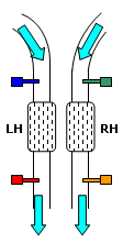
This time the customer reported bad surging at idle when the vehicle was warm, general poor running, and repeat DTC logging of LH BANK FRONT O2 SENSOR and RH BANK FRONT O2 SENSOR. The car was a Ferrari 355 1999 model incorporating catalyst efficiency monitoring. It had a V8 with a catalyst on each exhaust branch, making a total of four oxygen sensors. All sensors were essentially the same zirconia type with a 200 mV to 800 mV output, where the signal line is biased above ground potential.
The car had had both upstream sensors replaced by a dealer, but this didnĪ»t keep the MIL extinguished for long. Then a new MAF sensor and CTS were added to the repair inventory, but made no difference to the running of the car. I was introduced to the vehicle through a good friend who runs an injector service centre. The customer resorted to taking on the repair himself and wanted his injectors checked, thinking that this might be the root of his problems. The shop owner persuaded him not to go down this route just yet, and instead recommended that the fuel management be checked again.
Taking a rational look at the diagnosis so far, it didnĪ»t seem likely that two upstream O2 sensors had failed at the same time, not least because they were on different banks. At this early stage it would have been a fair prediction that a common cause existed, affecting the way both sensors operated, and not necessarily electrical. I approached the problem, as always, from the beginning by wanting to have a look at the operation of all four O2 sensors to build a bigger picture of the problem.
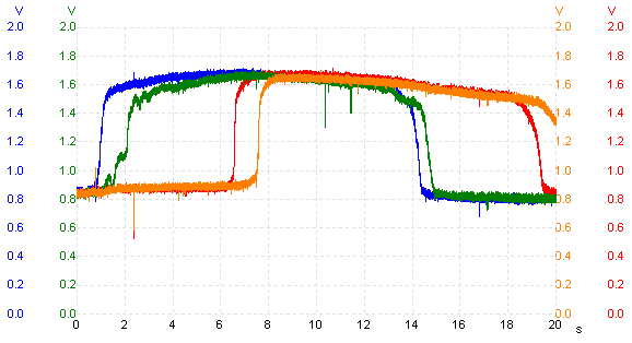
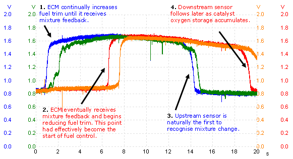
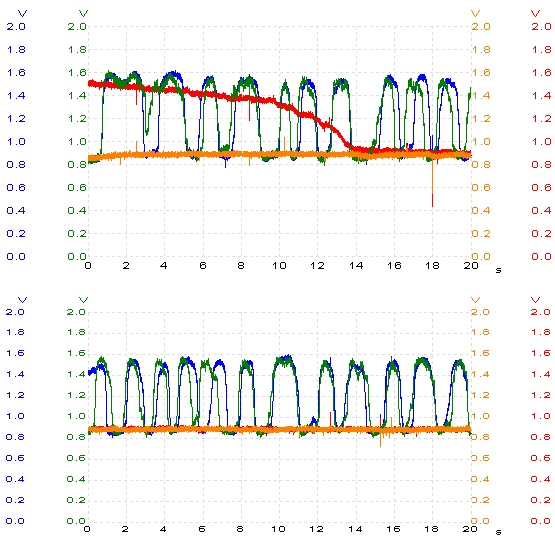
The above capture was taken with the engine idling hot, and itĪ»s far from what you would expect. WeĪ»ve completely lost our usual 1 Hz fuel control, which has been replaced with an approximately 0.03 Hz variation; a very poor signal, anyway. However, the overall signal trend is still well-defined and, if we allow for the presence of a running fault somewhere, all signal transitions and structure appear normal. ThereĪ»s the option available to zoom in and scrutinise signal transition times if we like but there is little point here, as something more serious is lurking.
Both banks are fuelling very similarly, as indicated by the two upstream sensors, so whatever the fault is itĪ»s affecting both banks. This agrees with the two DTCs logged at the beginning, and confirms the rational view we mentioned above. WhatĪ»s peculiar is that, despite this major running problem, the periods of rich and lean seem evenly balanced. Normally, a drivability fault of this magnitude swings the fuel mixture to one side of stoichiometric and stays there most of the time. The corresponding downstream units donĪ»t tell us much, except that the catalysts are present and oxygen storage capability is good. The long signal delay between upstream and downstream on each bank shows how well the catalysts are working.
Monitoring of the live data stream was hindered by a slow parameter update through the scan tool, although it did provide enough information to eliminate some peripheral factors and a few possible causes. Thus, it showed that the MAF and TPS relationship was good, fuel trim was chasing them to regain fuel control, and the O2 sensor voltages were in fact altering (this might seem incidental but it eliminates any open circuit in the sensor signal lines). All in all, things seemed normal. Some general checks in and around the engine bay, where the main areas covered were air intake and fuel delivery, didnĪ»t throw up much either. In short, I was struggling to find a solid link to the ECM so I turned back to the scope.
Watching the signal trends long enough and listening to the engine surging in the background, I spotted something I had missed earlier. There was an obvious correlation between the periodic surges and the sensor transitions, but it wasnĪ»t the upstream sensors that swung with engine rpm change Ī¬ it was the ones downstream. Fuel control was being influenced by the post-catalyst O2 sensors! A simple test to verify this was to disconnect the upstream sensors, which had no effect on the rpm surges; then disconnecting the downstream sensors stopped the surging and brought idle speed to something like normal. Why was the ECM so interested in the downstream sensors? This discovery now meant that all captures had to be re-evaluated.
There are ECM strategies to be aware of where a downstream sensor takes over fuel control from the upstream in case of failure, but I disregarded this as a possible contributing factor because I could see no reason for the ECM to doubt the upstream signalsĪ» validity. Also, the fault appeared as soon as the engine was warm and entering closed loop, so leaving no opportunity for the ECM to adequately monitor the sensorĪ»s performance.
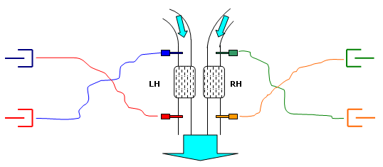
With all four sensors still disconnected, I was reminded of the obvious fact mentioned at the very beginning of this investigation: that all sensors had the same block connector and the same terminal assignment. Of course they were similar, because they were essentially all the same sensor. Then I noted how the sensors on both sides were mounted close together Ī¬ it would have been quite easy to pair the connectors wrongly. When I looked at this potential problem from the ECMĪ»s perspective, things started to make sense.
Before reversing the sensor connections I made sure that all DTCs were erased to start from clean. Deleting a code does not usually reset the adaptation, which is what was more important here - the two commands are very different. As long as I kept an eye on fuel trim and made sure it reacted accordingly, I should be all right. On start-up it didnĪ»t take long for the ECM to reply, and for both upstream sensors to begin to alternate in O2 concentration. Once fuel trim settled to single figures, a much more repetitive and stable switching frequency was recorded. When closed loop was fully under way, the downstream sensors followed closely behind by reporting excellent catalyst efficiency. Overall, everything was much better.
This was a mistake waiting to happen, as the coloured tape that usually distinguishes one mating pair from the other wasnĪ»t present on this vehicle. How the sensors became crossed in the first place never really came to light, as it often doesnĪ»t. For the majority of cars it would be difficult to accidentally create such a fault, as it is common to see different sensors fitted upstream and downstream; typically wideband units up-front with the trusted zirconia at the rear. Not only that, but general harness routing also makes it difficult to get it wrong. I suspect that this wonĪ»t be the last time that this model of vehicle gives someone a drivability head scratcher Ī¬ same sensors, same terminal assignment, same block connector, similar cable length, and same-side fixing locations.
Ųõ╦³▌oī¦┘Y┴Ž >
|